How to Tool path optimization | NX 2306 CAM
December 13, 2023 2024-11-11 14:21How to Tool path optimization | NX 2306 CAM
How to Tool path optimization | NX 2306 CAM
Overview Tool Path Optimization NX
In this TechTip, you’ll discover Tool Path Optimization how to optimize tool paths using the “Cut Area” method in Siemens NX 2306. Utilizing the Cut Area feature allows for enhanced control over tool paths, eliminating the necessity to create additional geometry to guide the tool.
For a more detailed walkthrough, please refer to the accompanying YouTube video. If you have any inquiries or need assistance. Please visit to login page here https://appv2.myigetit.com/auth/login. If you have active subscribtion of mygetit Tech Tip, Please reach out to https://app.myigetit.com/TechTips.
(Kindly ensure that you accept all cookies on the website hosting the video for a seamless viewing experience)
Step 1
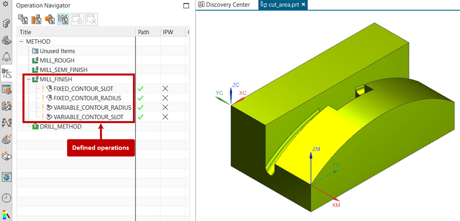
Open the part file cut_area.prt. This part already has several operations defined in Tool Path Optimization.
Step 2
Edit the operation Fixed Contour Slot and generate the operation Tool Path Optimization NX.
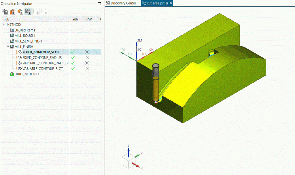
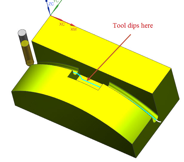
Notice that the tool dips into the pocket and while this does not harm anything, other than this may break the tool and thus this is not the desired tool path.
Step 3
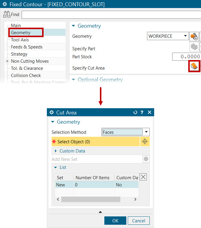
In the Fixed Contour Slot operation dialog, in the geometry tab, Click on Specify Cut Area option to display the Cut Area Dialog.
Step 4
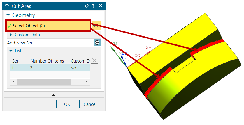
Select the two bottom faces of the groove to be the Cut Area and click OK in Cut Area Window.
Step 5
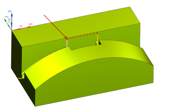
Generate the operation and notice that the cutter does not drop into the cutout. However, the cutter does retract where it is not necessary and this should get fixed.
Step 6
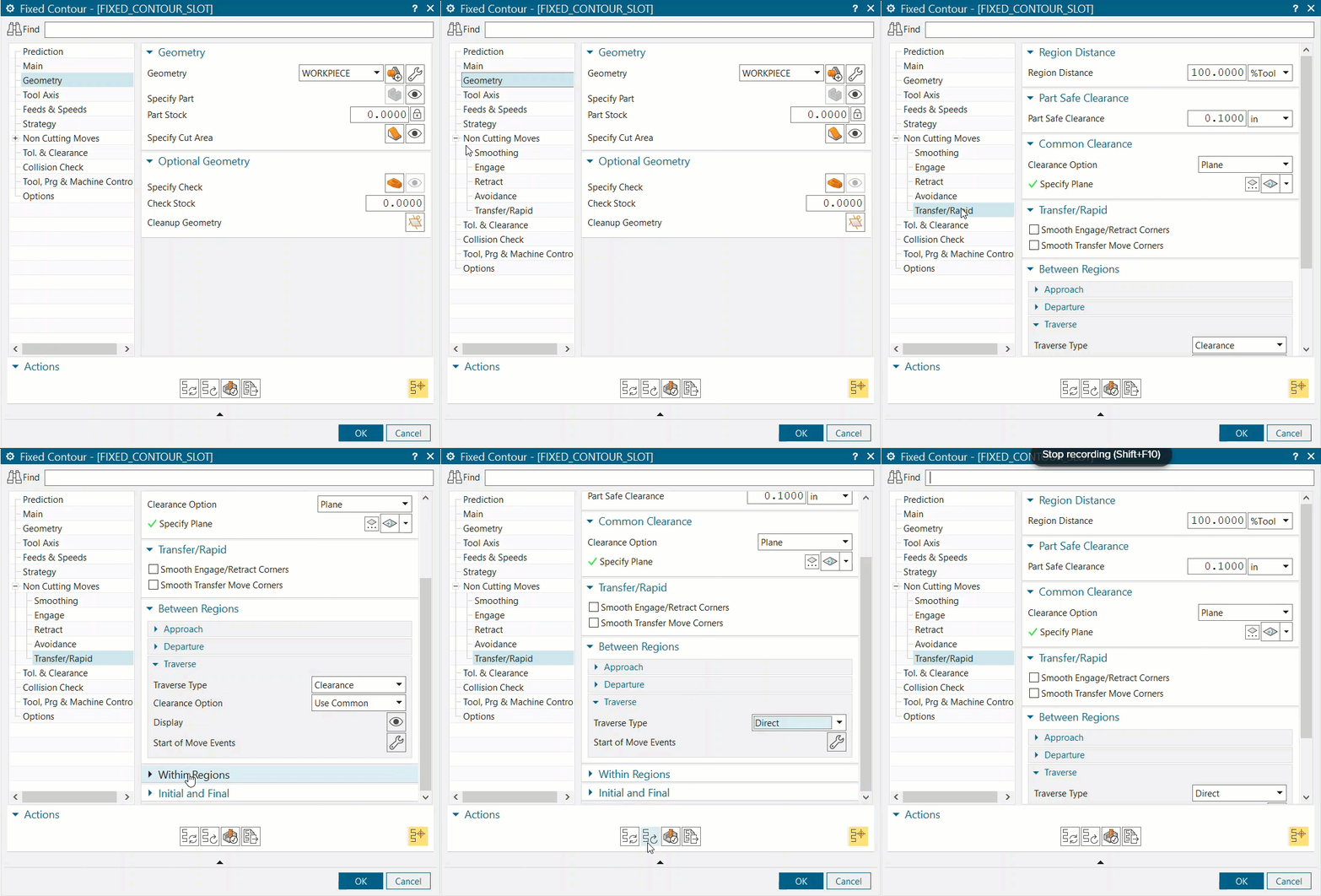
Expand the Non-Cutting Moves tab and in the Transfer or Rapid tab, expand the Between Regions group.
Then expand the Traverse group and here, change the Traverse Type to Direct and again generate the operation Tool Path Optimization NX.
Step 7

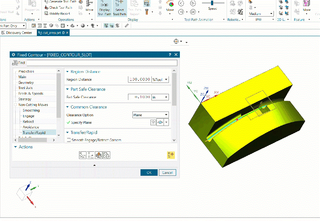
Now see that the cutter stays in feed mode and moves in a direct path to the next face, which is the required tool path.
Step 8
Verify the operation by specifying the Blank Geometry as shown
About i Get IT
i GET IT is our Tata Technologies eLearning solution designed to teach engineers how to be better in using today’s leading MCAD (Mechanical Computer Aided Design) applications and design skills.
For more tech tips and in-depth eLearning for Siemens NX, including this and new courses on other design solutions, please visit https://www.myigetit.com. You can sign up and get FREE Subscription of our informative Newsletter.
Start your Upskilling Journey Now! Visit our Plans Pages – https://myigetit.com/plans/
If you should have any questions, please reach out to iproducts@tatatechnologies.com or igetitsupport@tatatechnologies.com for help.
If you like our Tech Blogs do share them using following share this post icon.
Prateek Potnis
Prateek Potnis is a CAD expert and technical content writer, specializing in crafting authentic content focused on mCAD software solutions. With a graduation degree in Mechanical Engineering and extensive experience in the field of computer-aided design, he brings a wealth of knowledge and expertise to his writing endeavors.
Related Posts
What is PLM? – Product Lifecycle Management [Detailed Guide]
October 9, 2025
240 views
Lead-Acid vs. Lithium-Ion Batteries: Key Differences & Best Uses
June 13, 2025
544 views
Top AutoCAD 3D Commands & Shortcuts with Examples
April 9, 2025
2,240 views
What is Engineering Mechanics? – Introduction 101
March 10, 2025
1,502 views
How to Create Stitch Weld in Weldments using Autodesk Inventor?
November 15, 2024
627 views
Find
Categories
Latest Posts
Popular Tags
3DEXPERIENCE
ACES
Aerospace
Aircraft Cabin
Assembly
autocad
autodesk
Autodesk Inventor
Business
CAD
CAD courses
CAD Drawings
CAD Drawing view
CAM
cam and follower
Career
cars
CATIA V5
catiav5
Chamfer
corner relief
CREO
design engineering
Design Engineers
dimensioning
Engineering Education
ev
EV Engineer
GD&T
inventor
Mechanical engineering
NX
NX 2306
Online Certification
product design
PTC
Sketcher
Sketching
Solid Combine
solidworks
Spinal Bend
tech
tech tips
threaded stud work
Upskilling


