How to use Profile Tool Sketcher | 3DEXPERIENCE
October 27, 2023 2023-10-27 12:17How to use Profile Tool Sketcher | 3DEXPERIENCE
How to use Profile Tool Sketcher | 3DEXPERIENCE
Overview
The goal of this tech tip is to teach users how to generate continuous lines and arcs using the Profile tool in a CAD software’s Sketcher module. This skill is crucial for creating intricate 2D sketches as a foundation for 3D models. Users will learn to access the sketching environment, activate the Profile tool, create seamless lines and arcs, add dimensions and constraints if needed, exit the sketch mode, and use the resulting profile for 3D feature construction. Mastering this technique allows efficient translation of design concepts into precise CAD representations
Step 1: Positioned Sketch
The goal of this tech tip is to impart the ability to seamlessly generate continuous lines and arcs utilizing the Profile tool within the Sketcher module of a CAD (Computer-Aided Design) software.
Consequently, this skill is essential for designing intricate 2D sketches that form the basis for subsequent 3D models.
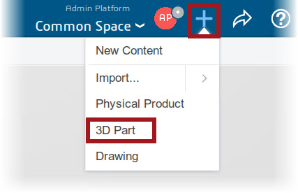
Step 2: Profile Tool

The “Profile tool” is a vital feature in CAD software used for creating 2D shapes and outlines. It enables users to draw continuous lines, arcs, and other geometric elements. By selecting this tool, designers can precisely sketch the foundational shapes necessary for building complex 3D models in the CAD environment.
Step 3: Tools Pallete
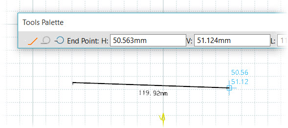
Within the Tools Palette of a CAD software, input the Horizontal (H) and Vertical (V) values for the initial point of your sketch. Upon pressing the TAB key, the text boxes dynamically update, allowing you to specify the endpoint coordinates.
Step 4: Creating Profile
To continue building a profile using the mentioned method, you consistently input Horizontal (H) and Vertical (V) values for each point’s coordinates in your CAD software’s Tools Palette. After pressing TAB, you iteratively define endpoint coordinates. This sequential process enables the creation of intricate profiles with precise control over position and dimension for each sketch element, ensuring accuracy in your CAD design.
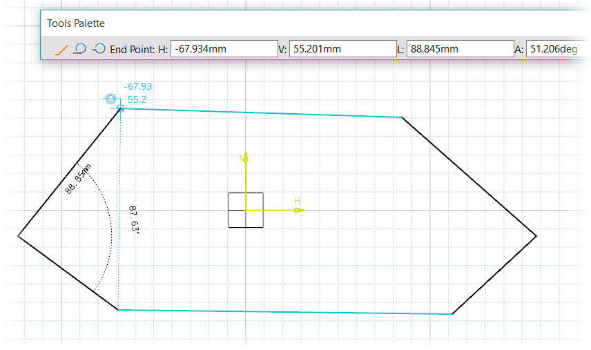
To finalize the profile you’re creating in CAD software, you have two common options:
Double-Click in the Graphics Window: One method is to double-click anywhere within the graphics window. This action signals the software to conclude the profile, automatically connecting the last point to the initial one, thus closing the shape.
Pick the Start Point in the Graphics Window: Alternatively, you can select the starting point of the profile by clicking on it in the graphics window. This manual closure allows you to have control over the exact connection point, which can be particularly useful when precision is critical in your design. Both methods help ensure that your profile forms a closed shape, which is often necessary for subsequent 3D modeling operations.
Step 5: Exit App

After completing your sketch in a CAD application, select the “Exit App” option to leave the sketching environment. It’s important to note that you typically don’t need to save this individual sketch as a separate part. Exiting without saving ensures that you return to the main workspace, ready to use the sketch as a basis for constructing 3D models without cluttering your project with unnecessary intermediate files.
Note: – To automatically select Tangent Arc, click and drag the cursor away from the created line, and release. When a geometric constraint symbol appears in the Graphics window, hold CTRL to lock that constraint.
About i GET IT
i GET IT is our Tata Technologies eLearning solution designed to teach engineers how to be better in using today’s leading MCAD (Mechanical Computer Aided Design) applications and design skills.
For more tech tips and in-depth eLearning for Autodesk, including this and new courses on other design solutions, please visit https://www.myigetit.com. You can sign up and get FREE Subscription of our informative Newsletter.
Start your Upskilling Journey Now! Visit our Plans Pages - https://myigetit.com/plans/
If you should have any questions, please reach out to iproducts@tatatechnologies.com or igetitsupport@tatatechnologies.com for help.
If you like our Tech Blogs do share them using following share this post icon.
Eric Bansen
Eric Bansen is a CAD expert with decade of experience in utilizing engineering CAD software to develop and evaluate automotive and product design concepts. He works as a Technical content manager for Tata Technologies and specializes in a range of software tools, including NX, SolidWorks, and AutoCAD.
Related Posts
What is PLM? – Product Lifecycle Management [Detailed Guide]
October 9, 2025
342 views
Lead-Acid vs. Lithium-Ion Batteries: Key Differences & Best Uses
June 13, 2025
634 views
Top AutoCAD 3D Commands & Shortcuts with Examples
April 9, 2025
2,373 views
What is Engineering Mechanics? – Introduction 101
March 10, 2025
1,608 views
How to Create Stitch Weld in Weldments using Autodesk Inventor?
November 15, 2024
725 views
Find
Categories
Latest Posts
Popular Tags
3DEXPERIENCE
ACES
Aerospace
Aircraft Cabin
Assembly
autocad
autodesk
Autodesk Inventor
Business
CAD
CAD courses
CAD Drawings
CAD Drawing view
CAM
cam and follower
Career
cars
CATIA V5
catiav5
Chamfer
corner relief
CREO
design engineering
Design Engineers
dimensioning
Engineering Education
ev
EV Engineer
GD&T
inventor
Mechanical engineering
NX
NX 2306
Online Certification
product design
PTC
Sketcher
Sketching
Solid Combine
solidworks
Spinal Bend
tech
tech tips
threaded stud work
Upskilling


